


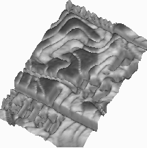
Figure: Three-dimensional Surface Representing a Selected Color Plane
(Red) for a Region of the ad250 Image from Figure 17.10
(Includes Letter ``P'' from ``Prachatice'' in the Upper Right Corner).
X,Y of the surface correspond to pixel coordinates and the Z value
of the surface is proportional to the image intensity.
Figure 17.17 presents a region from the ad250 image, displayed as a three-dimensional surface. The image pixel coordinates X,Y are mapped on the surface X,Y coordinates, whereas the Z value of the surface for a given X,Y is proportional to the local intensity value of a given color plane. In Figure 17.17, the red plane was taken; similar pictures can be obtained for green, blue, luminance, and any other plane filter. To identify the displayed region on the image, note the letter P-the first character in the ``Prachatice'' name in the upper-right corner of the surface and the number ``932'' below and left of it.
As seen, even if there are some local intensity fluctuations in the image, the resulting surface is reasonably smooth and the segmentation problem can also be addressed by using suitable edge detection techniques.
On an ``ideal'' map image, edges could be detected simply by identifying color discontinuities. On the ``real world'' map images, the edges are typically not very abrupt due to the A/D conversion process-it is more appropriate to think in terms of smooth surface fitting and analyzing rapid changes of the first derivatives or zeros of the second derivative. These types of techniques were developed originally by Marr and Hildreth [Marr:80a] and most recently by Canny [Canny:87a].
The single step of this algorithm looks as follows:
 ;
;
The result of the Canny filter applied to the
ad250 image is presented in Figure 17.18. Each pixel is
represented there as a  color square and the neighboring
squares are separated by a one-pixel-wide black background. Zero
crossings of D are marked as white segments and they always form closed
contours.
color square and the neighboring
squares are separated by a one-pixel-wide black background. Zero
crossings of D are marked as white segments and they always form closed
contours.
As seen, the brown isoclines which required substantial labor to be separated by the RGB clustering techniques are now detected in a very easy and clean way. However, there is also some number of spurious contours in Figure 17.18 which are to be rejected. The simplest signal-to-noise-based selection technique could be as follows:
A natural use of the Canny filter in Figure 17.18 could be as follows. The image is first segmented into Canny contours which are threshold as above and then labelled. For each contour, an average color is computed by integrating the color context enclosed by this contour. This reduced color palette is then used as input to the RGB clustering. Such an approach would guarantee, for example, that all brown isoclines in Figure 17.10 will be detected as smooth lines, contrary to both RGB clustering and neural network algorithms, which occasionally fail to reconstruct continuous isoclines.
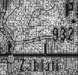
Figure: Output of the Canny Edge Detector Filter, Applied to a Region of the
Image ad250 from Figure 17.10. Closed contours
are zero crossings of the second directional derivative, taken in the
direction of local intensity gradient.
Consider, however, a ``Mexican hat''-shaped green patch in
Figure 17.10, located in the upper left part of the image,
between Prachatice name and 932 number. This patch was very easily and
correctly detected by both RGB clustering and by the neural net, but we would
fail to detect it by the single step Canny filter described above. Indeed,
after careful inspection of the contours in Figure 17.18, one can
notice that there is no single closed zero crossing line encircling this
region. In consequence, any contour-based color averaging procedure as above
would result in some green color ``leakage.'' Within the Canny edge detection
program, such edges are detected using the multiscale approach. The base
algorithm outlined above is iterated with the increasing value of the
Gaussian width  and some multiscale
acceptance/rejection method is employed. The green patch would
eventually manifest as a low-frequency edge for some sufficiently large
value of
and some multiscale
acceptance/rejection method is employed. The green patch would
eventually manifest as a low-frequency edge for some sufficiently large
value of  .
.
We intend to investigate in more detail such multiresolution edge-detection strategies. In our opinion, however, a more attractive approach is based on hybrid techniques, discussed in the next Section.