

Equation 3.1 first stated our approach to computation as a map between different complex systems. We can quantify this by defining a partial order on complex systems written
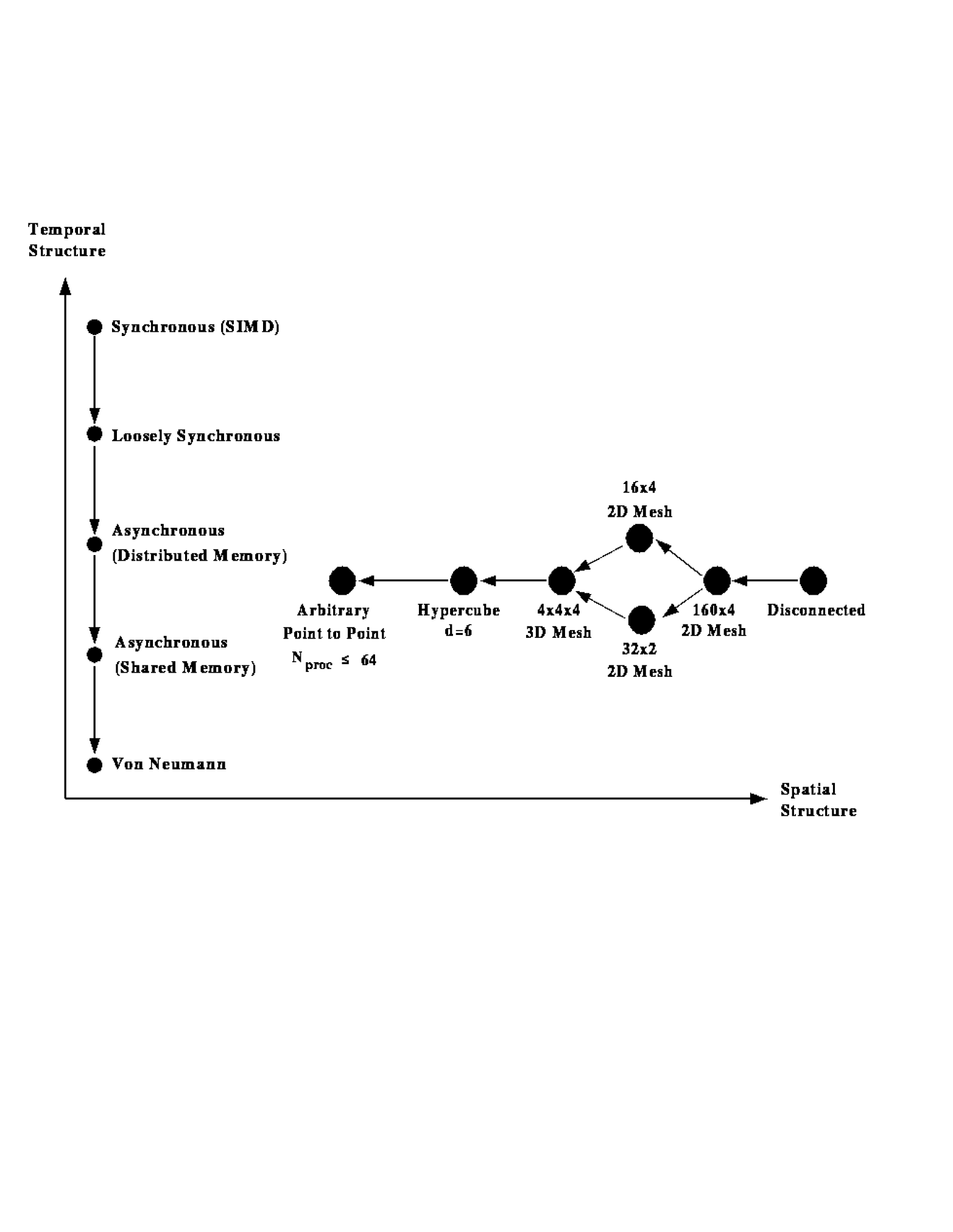
Equation 3.17 states that a complex system A can be mapped to complex system B, that is, that B has a more general architecture than A. This was already seen in Figure 3.8 and is given in more detail in Figure 3.12, where we have represented complex systems in a two-dimensional space labelled by their spatial and temporal properties. In this notation, we require:

Figure 3.12: An Illustration of Problem or Computer Architecture Represented
in a Two-dimensional Space. The spatial structure only gives a few
examples.
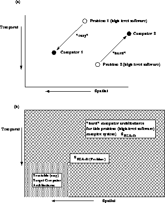
The requirement that a particular problem parallelize is that
which is shown in Figure 3.13. We have drawn our space
labelled by complex system properties so that the partial ordering of
Figures 3.8 and 3.12 ``flows'' towards the
origin. Roughly, complex systems get more specialized as one either moves
upwards or to the right. We view the three key complex systems,
 ,
,  , and
, and  , as points in the space
represented in Figures 3.12 and 3.13.
Then Figure 3.13 shows that the computer complex system
 lies below and to the left of those representing
  and
and  .
.
Let us consider an example. Suppose  (the computer) is a
hypercube of dimension
  with a MIMD temporal
structure. Synchronous, loosely
synchronous, or asynchronous problems can be mapped onto this computer
as long as the problem's spatial structure is contained in the
hypercube topology. Thus, we will successfully map a
  two-dimensional mesh. But what about a
  mesh or
 irregular lattice? The
  mesh only
has nine (spatial) components and insufficient parallelism to exploit
the 64-node computer. The large irregular mesh can be efficiently
mapped onto the hypercube as shown in Chapter 12. However, one
could support this with a more general computer architecture where
hardware or software routing essentially gives the general node-to-node
communication shown in the bottom left corner of
Figure 3.12. The hypercube work at Caltech and elsewhere
always used this strategy in mapping complex spatial topologies; the
crystal-router mechanism in CrOS or Express was a powerful and
efficient software strategy. Some of the early work using
transputers found difficulties with some spatial
structures since the language
Occam only directly supported process-to-process
communication over the physical hardware channels. However, later
general Occam subroutine libraries (communication ``harnesses'')
callable from FORTRAN or C allowed the general point-to-point
(process-to-process) communication model for transputer systems.

Figure: Easy and Hard Mappings of Complex Systems  or
or  . We show
complex systems for problems and computers in a space labelled by
spatial and temporal complex system (computer architectures).
Figure 3.12 illustrates possible ordering of
these structures.


