

An important class of problems are those which model a continuum system by discretizing continuous space with a mesh. Figure 11.2 shows an unstructured triangular mesh surrounding a cross-section of a four-element airfoil from an Airbus A-310. The variations in mesh density are caused by the nature of the calculation for which the mesh has been used; the airfoil is flying at Mach 0.8 to the left, so that a vertical shock extends upward at the trailing edge of the main airfoil, which is reflected in the increased mesh density.
The mesh has been split among 16 processors of a distributed machine, with the divisions between processors shown by heavy lines. Although the areas of the processor domains are different, the numbers of triangles or elements assigned to the processors are essentially the same. Since the work done by a processor in this case is the same for each triangle, the workloads for the processors are the same. In addition, the elements have been assigned to processors so that the number of adjacent elements which are in different processors is minimized.
In order to analyze the optimal distribution of elements among the processors, we must consider the way the processors need to exchange data during a calculation. In order to design a general load balancer for such calculations, we would like to specify this behavior with the fewest possible parameters, which do not depend on the particular mesh being distributed. The following remarks apply to several application codes, written to run with the DIME software (Section 10.1), which use two-dimensional unstructured meshes, as follows:\
As far as load balancing is concerned, all of these codes are rather similar. This is because the algorithms used are local: Each element or node of the mesh gets data from its neighboring elements or nodes. In addition, a small amount of global data is needed; for example, when solving iteratively, each processor calculates the norm of the residual over its part of the mesh, and all the processors need the minimum value of this to decide if the solve has converged.
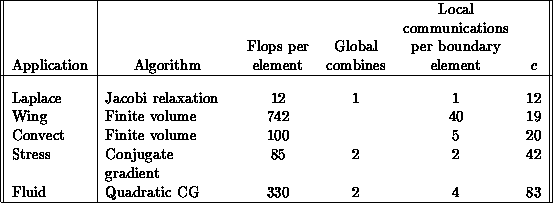
We can analyze the performance of code using an approach similar to that in Section 3.5. In this case, the computational kernel of each of these applications is iterative, and each iteration may be characterized by three numbers:\
These numbers are listed in the following table for the five applications listed above:\

The two finite-volume applications do not have iterative matrix solves, so they have no convergence checking and thus have no need for any global data exchange. The ratio c in the last column is the ratio of the third to the fifth columns and may be construed as follows. Suppose a processor has E elements, of which B are at the processor boundary. Then the amount of communication the processor must do compared to the amount of calculation is given by the general form of Equation 3.10, which here becomes

It follows that a large value of c corresponds to an eminently
parallelizable operation, since the communication rate is low compared to
calculation. The ``Stress'' example has a high value of c because the
solution being sought is a two-dimensional strain field; while the
communication is doubled, the calculation is quadrupled, because the elements
of the scalar stiffness matrix are replaced by  block matrices,
and each block requires four multiplies instead of one. For the ``Fluid''
example, with quadratic elements, there are the two components of velocity
being communicated at both nodes and edges, which is a factor of four for
communication, but the local stiffness matrix is now
  because
of the quadratic elements. Thus, we conclude that the more interacting
fields, and the higher the element order, the more efficiently the
application runs in parallel.


