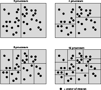
Figure 10.7: Recursive Bisection


When DIME operates in parallel, the mesh should be distributed among the processors of the machine so that each processor has about the same amount of mesh to deal with, and the communication time is as small as possible. There are several ways to do this, such as with a computational neural net, by simulated annealing, or even interactively.
DIME uses a strategy known as recursive bisection [Fox:88mm], which has the advantages of being robust, simple, and deterministic, though sometimes the resulting communication pattern may be less than optimal. The method is illustrated in Figure 10.7: each blob represents the center of an element, and the vertical and horizontal lines represent processor divisions. First, a median vertical line is found which splits the set of elements into two sets of approximately equal numbers, then (with two-way parallelism) two horizontal medians which split the halves into four approximately equal quarters, then (with four-way parallelism) four vertical medians, and so on. Chapter 11 describes more general and powerful load-balancing methods.

Figure 10.7: Recursive Bisection
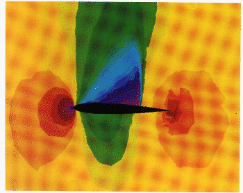
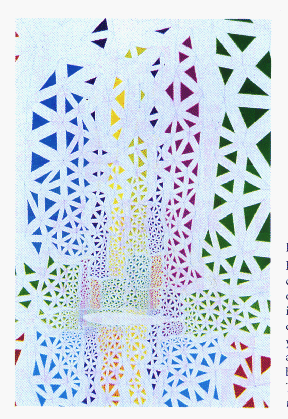
Figure 10.8 (Color Plate) and Figure 10.9 (Color Plate) are from a calculation of transonic flow over an airfoil (see Section 12.3). Figure 10.9 shows the parallel structure of the DIME mesh used to calculate the flow. The redundant copies of shared nodes have been separated to show the data connections between them in yellow and blue.

Figure : Pressure plot Mach 0.8 flow over a NACA0012
airfoil, with the sonic line shown. The mesh for this computation is shown
in Figure 10.9.

Figure 10.9: Depiction of the mesh for the transonic
flow calculation of color Figure 10.8. Each group of similarly colored
triangles is owned by an individual processor. The mesh has been
dynamically adapted and load-balanced. The yellow lines connect copies of
nodes which are in the same geometric positioin, but have been separated
for the purpose of this picture. The load balancing is by orthogonal
recursive bisection.
In the pressure plot, there is a vertical shock about two-thirds of the way downstream from the leading edge of the airfoil. This can also be seen in the mesh plot since the same region has especially small triangles and high mesh density. Since each processor has about the same number of triangles, the processor regions are also small in the neighborhood of the shock.


