Figure 10.2: Major Components of DIME


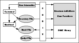
Figure 10.2 shows the structure of a DIME application. The shaded parts represent the contribution from the user, being a definition of a domain which is to be meshed, a definition of the data to be maintained at each element, node, and boundary edge of the mesh, and a set of functions that manipulate this data. The user may also supply or create a script file for running the code in batch mode.

Figure 10.2: Major Components of DIME
The first input is the definition of a domain to be meshed. A file may be made using the elementary CAD program curvetool, which allows straight lines, arcs, and cubic splines to be manipulated interactively to define a domain.
Before sending a domain to a DIME application, it must be predigested to some extent, with the help of a human. The user must produce a coarse mesh that defines the topology of the domain to the machine. This is done with the program meshtool, which allows the user to create nodes and connect them to form a triangulation.
The user writes a program for the mesh, and this program is loaded into each processor of the parallel machine. When the DIME function readmesh() is called, (or ``Readmesh'' clicked on the menu), the mesh created by meshtool is read into a single processor, and then the function balance_orb() may be called (or ``Balance'' clicked on the menu) to split the mesh into domains, one domain for each processor.
The user may also call the function writemesh() (or click ``Writemesh'' in the menu), which causes the parallel mesh to be written to disk. If that mesh is subsequently read in, it is read in its domain-decomposed form, with different pieces assigned to different processors.
In Figure 10.2, the Cubix server is not mandatory, but only needed if the DIME application is to run in parallel. The application also runs on a sequential machine, which is considered to be a one-processor parallel machine.


