The P processes of an abstract
parallel computer are often represented
as a one-dimensional linear array of
processes labeled ![]() .
For reasons described below, it is often
more convenient to map this one-dimensional
array of processes into a two-dimensional
rectangular grid, or process grid.
(A process grid is also referred to as a
process mesh.)
This grid will have
.
For reasons described below, it is often
more convenient to map this one-dimensional
array of processes into a two-dimensional
rectangular grid, or process grid.
(A process grid is also referred to as a
process mesh.)
This grid will have ![]() process rows
and
process rows
and ![]() process columns, where
process columns, where ![]() . A process can now be
referenced by its row and column coordinates,
(
. A process can now be
referenced by its row and column coordinates,
(![]() ), within the grid, where
), within the grid, where ![]() ,
and
,
and ![]() ). An example of
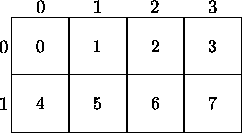
such a mapping is shown in figure 4.1,
where
). An example of
such a mapping is shown in figure 4.1,
where ![]() and
and ![]() .
.

Figure 4.1: Eight processes mapped to a ![]() process grid
process grid
In figure 4.1, the processes are mapped to the process grid by using row-major order ; in other words, the numbering of the processes increases sequentially across each row. Similarly, the processes can be mapped in a column-major order whereby the numbering of the processes proceeds down each column of the process grid. The BLACS routine BLACS_GRIDINIT performs this task of mapping the processes to the process grid. By default, BLACS_GRIDINIT assumes a row-major ordering, although a column-major ordering can also be specified. The companion routine BLACS_GRIDMAP is a more general form of BLACS_GRIDINIT and allows the user to define the mapping of the processes . Refer to the Appendix D.3 for further details.
All ScaLAPACK routines, with the exception of the band linear system routines, allow the processes to be viewed as a one-dimensional or two-dimensional process grid. The band routines support only one-dimensional process grids.