 to
to
 automata. Trial application runs included two-dimensional, vertical,
time-dependent flows in several geometries, of which two examples are given
here: Couette flow and flow out of an hourglass-shaped
hopper.


The LGrM simulations performed so far have involved from  to
to
 automata. Trial application runs included two-dimensional, vertical,
time-dependent flows in several geometries, of which two examples are given
here: Couette flow and flow out of an hourglass-shaped
hopper.
The standard Couette flow configuration consists of a fluid confined between two flat parallel plates of infinite extent, without any gravitational accelerations. The plates move in opposite directions with velocities that are equal and parallel to their surfaces, which results in the establishment of a velocity gradient and a shear stress in the fluid. For fluids that obey the Navier-Stokes equation, an analytical solution is possible in which the velocity gradient and shear stress are constant across the channel. If, however, we replace the fluid by a system of inelastic grains, the velocity gradient will no longer necessarily be constant across the channel. Typically, stagnation zones or plugs form in the center of the channel with thin shear-bands near the walls. Shear-band formation in flowing granular materials was analyzed earlier by Haff and others [Haff:83a], [Hui:84a] based on kinetic theory models.
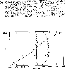
The simulation was carried out with 5760 grains, located in a channel 60 lattice points wide by 192 long. Due to the periodic boundary conditions at the left and right ends, the problem is effectively infinite in length. The first simulation is intended to reproduce the standard Couette flow for a fluid; consequently, the particle-particle collisions were given a coefficient of restitution of 1.0 (i.e., perfectly elastic collisions) and the particle-wall collisions were given a .75 coefficient of restitution. The inelasticity of the particle-wall collisions is needed to simulate the conduction of heat (which is being generated within the fluid) from the fluid to the walls. The simulation was run until an equilibrium was established in the channel (Figure 4.26(a)). The average x- and y-components of velocity and the second moment of velocity, as functions of distance across the channel, are plotted in Figure 4.26(b).

Figure 4.26: (a) Elastic Particle Couette Flow; (b) x-component (1),
y-component (2), and Second Moment (3) of Velocity
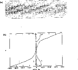
The second simulation used a coefficient of restitution of .75 for both the particle-particle and particle-wall collisions. The equilibrium results are shown in Figure 4.27(a) and (b). As can be seen from the plots, the flow consists of a central region of particles compacted into a plug, with each particle having almost no velocity. Near each of the moving walls, a region of much lower density has formed in which most of the shearing motion occurs. Note the increase in value of the second moment of velocity (the granular ``thermal velocity'') near the walls, indicating that grains in this area are being ``heated'' by the high rate of shear. It is interesting to note that these flows are turbulent in the sense that shear stress is a quadratic, not a linear, function of shear rate.

Figure 4.27: (a) Inelastic Particle Couette Flow; (b) x-component (1),
y-component (2), and Second Moment (3) of Velocity.
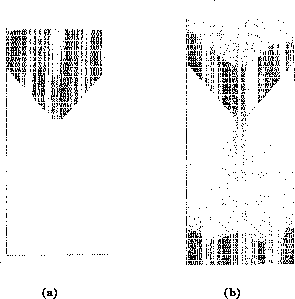
In the second problem, the flow of grains through a hopper or an hourglass with an opening only a few grain diameters wide, was studied; the driving force was gravity. This is an example of a granular system which contains a wide range of densities, from groups of grains in static contact with one another to groups of highly agitated grains undergoing true binary collisions. Here, the number of particles used was 8310, and the lattice was 240 points long by 122 wide. Additional walls were added to form the sloped sides of the bin and to close off the bottom of the lattice to prevent the periodic boundary conditions from reintroducing the falling particles back into the bin (Figure 4.28(a)). This is a typical feature of automata modelling. It is often easier to configure the simulation to resemble a real experiment-in this case by explicitly ``catching'' spent grains-than by reprogramming the basic code to erase such particles.
The hourglass flow in Figure 4.28(b) showed internal shear zones, regions of stagnation, free-surface evolution toward an angle of repose, and an exit flow rate approximately independent of pressure head, as observed experimentally [Tuzun:82a]. It is hard to imagine that one could solve a partial differential equation describing such a complex, multiple-domain, time-dependent problem, even if the right equation were known (which is not the case).

Figure 4.28: (a) Initial Condition of Hourglass; (b) Hourglass Flow after 2048
Time Steps


