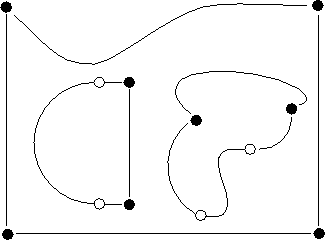
Figure 10.3: Boundary Structure


Figure 10.3 shows an example of a DIME boundary structure. The filled blobs are points, with curves connecting the points. Each curve may consist of a set of curve segments, shown in the figure separated by open circles. The curve segments may be straight lines, arcs of circles, or Bezier cubic sections. The program curvetool is for the interactive production of boundary files. When the domain is satisfactory, it should be meshed using meshtool.

Figure 10.3: Boundary Structure
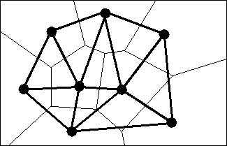
The program meshtool is used for defining boundaries and creating a triangulation of certain regions of a grid. Meshtool adds nodes to an existing triangulation using the Delaunay triangulation [Bowyer:81a]. A new node may be added anywhere except at the position of an existing node. Figure 10.4 illustrates how the Delaunay triangulation (thick gray lines) is derived from the Voronoi tesselation (thin black lines).

Figure 10.4: Voronoi Tesselation and Resulting Delaunay Triangulation
Each node (shown by a blob in the figure) has a ``territory,'' or Voronoi polygon, which is the part of the plane closer to the node than to any other node. The divisions between these territories are shown as thin lines in the figure, and are the perpendicular bisectors of the lines between the nodes. This procedure tesselates the plane into a set of disjoint polygons and is called the Voronoi tesselation. Joining nodes whose Voronoi polygons have a common border creates a triangulation of the nodes known as the Delaunay triangulation. This triangulation has some desirable properties, such as the diagonal dominance of a finite-element stiffness matrix derived from the mesh [Young:71a].