 , is given by


A group at JPL, led by Jean Patterson, developed several hypercube codes for the solution of large-scale electromagnetic scattering and radiation problems. Two codes were parallel implementations of standard production-level EM analysis codes and the remaining are largely or entirely new. Included in the parallel implementations of existing codes is the widely used numerical electromagnetics code (NEC-2) developed at Lawrence Livermore National Laboratory. Other codes include an integral equation formulation Patch code, a time-domain finite-difference code, a three-dimensional finite-elements code, and infinite and finite frequency selective surfaces codes. Currently, we are developing an anisotropic material modeling capability for the three-dimensional Finite Elements code and a three-dimensional coupled approach code. In the Coupled Approach, one uses finite elements to represent the interior of a scattering object, and the boundary integrals for the exterior. Along with the analysis tools, we are developing an Electromagnetic Interactive Analysis Workstation (EIAW) as an integrated environment to aid in design and analysis. The workstation provides a general user interface for specification of an object to be analyzed and graphical representations of the results. The EIAW environment is implemented on an Apollo DN4500 Color Graphics Workstation, and a Sun Sparc2. This environment provides a uniform user interface for accessing the available parallel processor resources (e.g., the JPL/Caltech Mark IIIfp and the Intel iPSC/860 hypercubes.) [Calalo:89b].
One of the areas of current emphasis is the development of the
anisotropic three-dimensional finite element analysis tool. We briefly
describe this effort here. The finite element method is being used to
compute solutions to open region electromagnetic scattering problems
where the domain may be irregularly shaped and contain differing
material properties. Such a scattering object may be composed of
dielectric and conducting materials, possibly with anisotropic and
inhomogeneous dielectric properties. The domain is discretized by a
mesh of polygonal (two-dimensional) and polyhedral (three-dimensional)
elements with nodal points at the corners. The finite element solution
that determines the field quantities at these nodal points is stated
using the Helmholtz equation. It is derived from Maxwell's
equations describing the incident and
scattered field for a particular wave number, k. The two-dimensional
equation for the out-of-plane magnetic field,  , is given by
where  is the relative permittivity and
  is the relative
magnetic permeability. The equation for the electric field is similarly
stated, interchanging
  and
and  .
.
The open region problem is solved in a finite domain by imposing an
artificial boundary condition for a circular boundary. For the
two-dimensional case, we are applying the approach of Bayliss and Turkel
[Bayliss:80a]. The cylindrical artificial boundary condition on
scattered field,  (where
  ), is given
by
where  is the radius of artificial boundary,
  is the
angular coordinate, and A and B are operators that are dependent on
 .
.
The differential Equation 9.7 can be converted to an integral equation by multiplying by a test function which has certain continuity properties. If the total field is expressed in terms of the incident and scattered fields, then we may substitute Equation 9.8 to arrive at our weak form equation
where F is the excitation, which depends on the incident field.
Substituting the field and test function representations in terms of nodal basis functions into Equation 9.9 forms a set of linear equations for the coefficients of the basis functions. The matrix which results from this finite-element approximation is sparse with nonzero elements clustered about the diagonal.
The solution technique for the finite-element problem is based on a domain decomposition . This decomposition technique divides the physical problem space among the processors of the hypercube. While elements are the exclusive responsibility of hypercube processors, the nodal points on the boundaries of the subdomains are shared. Because shared nodal points require that there be communication between hypercube processors, it is important for processing efficiency to minimize the number of these shared nodal points.
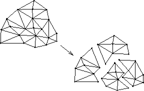
Figure 9.5: Domain Decomposition of the Finite Element Mesh into Subdomains,
Each of Which are Assigned to Different Hypercube Processors.
The tedious process of specifying the finite-element model to describe the geometry of the scattering object is greatly simplified by invoking the graphical editor, PATRAN-Plus, within the Hypercube Electromagnetics Interactive Analysis Workstation. The graphical input is used to generate the finite-element mesh. Currently, we have implemented isoparametric three-node triangular, six-node triangular, and nine-node quadrilateral elements for the two-dimensional case, and linear four-node tetrahedral elements for the three-dimensional case.
Once the finite-element mesh has been generated, the elements are allocated to hypercube processors with the aid of a partitioning tool which we have developed. In order to achieve good load balance, each of the hypercube processors should receive approximately the same number of elements (which reflects the computation load) and the same number of subdomain edges (which reflects the communication requirement). The recursive inertial partitioning (RIP) algorithm chooses the best bisection axis of the mesh based on calculated moments of inertia. Figure 9.6 illustrates one possible partitioning for a dielectric cylinder.
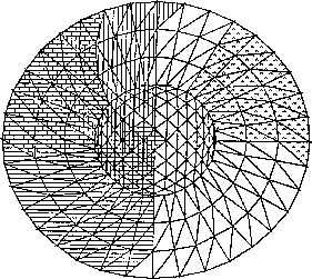
Figure 9.6: Finite Element Mesh for a Dielectric Cylinder Partitioned Among
Eight Hypercube Processors
The finite-element problem can be solved using several different strategies: iterative solution, direct solution, or a hybrid of the two. We employ all of these techniques in our finite elements testbed. We use a preconditioned biconjugate gradients approach for iterative solutions and a Crout solver for the direct solution [Peterson:85d;86a]. We also have developed a hybrid solver which uses first Gaussian elimination locally within hypercube processors, and then biconjugate gradients to resolve the remaining degrees of freedom [Nour-Omid:87b].
The output from the finite elements code is displayed graphically at the Electromagnetics Interactive Analysis Workstation. In Figure 9.7 (Color Plate) are plotted the real (on the left) and the imaginary (on the right) components of the total scalar field for a conducting cylinder of ka=50. The absorbing boundary is placed at kr=62. Figure 9.8 (Color Plate) shows the plane wave propagation indicated by vectors in a rectangular box (no scatterer). The box is modeled using linear tetrahedral elements. Figure 9.9 (Color Plate) shows the plane wave propagation (no scatterer) in a spherical domain, again using tetrahedral linear elements. The half slices show the internal fields. In the upper left is the x-component of the field, the lower left is the z-component, and on the right is the y-component with the fields shown as contours on the surface.
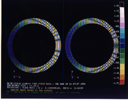
Figure 9.7: Results from the two-dimensional
electromagnetic scalar finite-element code described in the text.
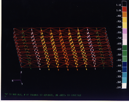
Figure 9.8: Test case for the electromagnetic
three-dimensional code with no scatterer described in text.
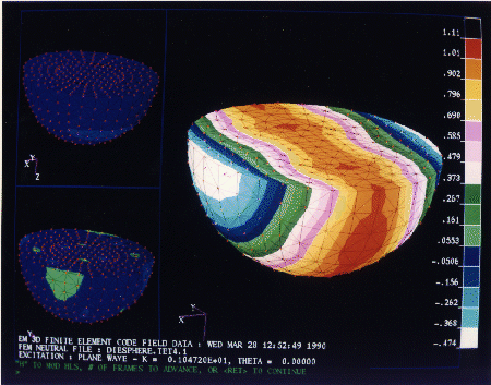
Figure 9.9: Test case for electromagnetic
three-dimensional planewave in spherical domain with no scatterer describes
in the text.
The speedups over the problem running on one processor are plotted for hypercube configurations ranging from 1 to 32 processors in Figure 9.10. The problem for this set of runs is a two-dimensional dielectric cylinder model consisting of 9313 nodes.
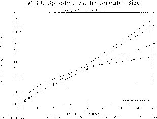
Figure 9.10: Finite-Element Execution Speedup Versus Hypercube Size
The setup and solve portions of the total execution time demonstrate 87% and 81% efficiencies, respectively. The output portion where the results obtained by each processor are sent back to the workstation run at about 50% efficiency. The input routine exhibits no speedup and greatly reduces the overall efficiency, 63% of the code. Clearly, this is an area on which we now must focus. We have recently implemented the partitioning code on parallel. We are also now reducing the size of the input file by compressing the contents of the mesh data file and removing formatted reads and writes. We are also developing a parallel mesh partitioner which iteratively refines a coarse mesh which was generated by the graphics software.
We are currently exploring a number of accuracy issues with regards to the finite elements and coupled approach solutions. Such issues include gridding density, element types, placement of artificial boundaries, and specification of basis functions. We are investigating outgoing wave boundary conditions; currently, we are using a modified Sommerfield radiation condition in three dimensions. In addition, we are exploring a number of higher order element types for three dimensions. Central to our investigations is the objective of developing analysis techniques for massive three-dimensional problems.
We have demonstrated that the parallel processing environments offered by the current coarse-grain MIMD architectures are very well suited to the solution of large-scale electromagnetic scattering and radiation problems. We have developed a number of parallel EM analysis codes that currently run in production mode. These codes are being embedded in a Hypercube Electromagnetic Interactive Analysis Workstation. The workstation environment simplifies the user specification of the model geometry and material properties, and the input of run parameters. The workstation also provides an ideal environment for graphically viewing the resulting currents and near- and far-fields. We are continuing to explore a number of issues to fully exploit the capabilities of this large-memory, high-performance computing environment. We are also investigating improved matrix solvers for both dense and sparse matrices, and have implemented out-of-core solving techniques, which will prevent us from becoming memory-limited. By establishing testbeds, such as the finite-element one described here, we will continue to explore issues that will maintain computational accuracy, while reducing the overall computation time for EM scattering and radiation analysis problems.


