


This subclass of machines is practically equivalent to the
single-processor vectorprocessors, although other interesting machines
in this subclass have existed (viz. VLIW machines
[31]). In the block
diagram in Figure 1 we depict a generic model of
a vector architecture.
The single-processor vector machine will have only one of the
vectorprocessors depicted and the system may even have its scalar
floating-point capability shared with the vector processor (as was the
case in some Cray systems). It may be noted
that the VPU does not show a cache. The majority of vectorprocessors do
not employ a cache anymore. In many cases the vector unit cannot take
advantage of it and execution speed may even be unfavourably affected
because of frequent cache overflow.
Although vectorprocessors have existed that loaded their operands
directly from memory and stored the results again immediately in
memory (CDC Cyber 205, ETA-10), all present-day vectorprocessors use
vector registers. This usually does not impair the speed of operations
while providing much more flexibility in gathering operands and
manipulation with intermediate results.
Because of the generic nature of Figure 1 no
details of the interconnection between the VPU and the memory are
shown. Still, these details are very important for the effective speed
of a vector operation: when the bandwidth between memory and the VPU is
too small it is not possible to take full advantage of the VPU because
it has to wait for operands and/or has to wait before it can store
results. When the ratio of arithmetic to load/store operations is not
high enough to compensate for such situations, severe performance
losses may be incurred.
The influence of the number of load/store paths for the dyadic vector
operation c = a + b (a, b, and c vectors)
is depicted in 2.
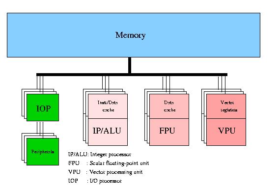
Figure 1:
Block diagram of a vector processor.
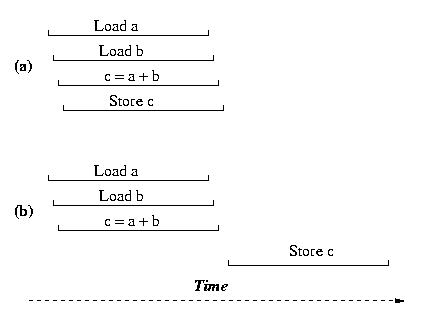
Figure 2:
Schematic diagram of a vector addition. Case (a) when two load-
and one store pipe are available; case (b) when two load/store pipes are
available.
Because of the high costs of implementing these datapaths between memory and the VPU, often compromises are sought and the number of systems that have the full required bandwidth (i.e., two load operations and one store operation at the same time) is limited. In fact, in the vector systems marketed today this high bandwidth thus not occur any longer. Vendors rather rely on additional caches and other tricks to hide the lack of bandwidth.
The VPUs are shown as a single block in Figure 1. Yet, again there is a considerable diversity in the structure of VPUs. Every VPU consists of a number of vector functional units, or "pipes" that fulfill one or several functions in the VPU. Every VPU will have pipes that are designated to perform memory access functions, thus assuring the timely delivery of operands to the arithmetic pipes and of storing the results in memory again. Usually there will be several arithmetic functional units for integer/logical arithmetic, for floating-point addition, for multiplication and sometimes a combination of both, a so-called compound operation. Division is performed by an iterative procedure, table look-up, or a combination of both using the add and multiply pipe. In addition, there will almost always be a mask pipe to enable operation on a selected subset of elements in a vector of operands. Lastly, such sets of vector pipes can be replicated within one VPU (2- up to 16-fold replication are occurs). Ideally, this will increase the performance per VPU by the same factor provided the bandwidth to memory is adequate.